Hobart AM 14 Wiring Diagrams for Authorized Technicians
Hobart AM 14 Series Dishwashers are used in a wide variety of commercial kitchens. When service technicians are called to make repairs inside the unit, having the right resources are crucial. Wiring diagrams can be a tech's best friend. These drawing show electrical systems or circuits in a machine, including where components and terminals appear and how they connect. This makes it easier to tackle any repair, installation or detailed troubleshooting. If you don't have them readily available, below are Hobart AM 14 wiring diagrams to use for reference.
NOTE: These diagrams are only for authorized Hobart technicians. Equipment operators should contact a local Hobart service agent to conduct the tasks outlined below as well as additional repairs.
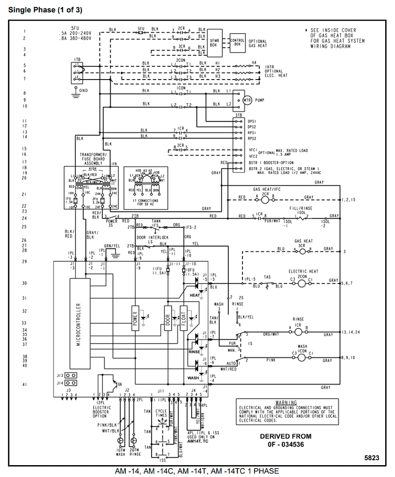
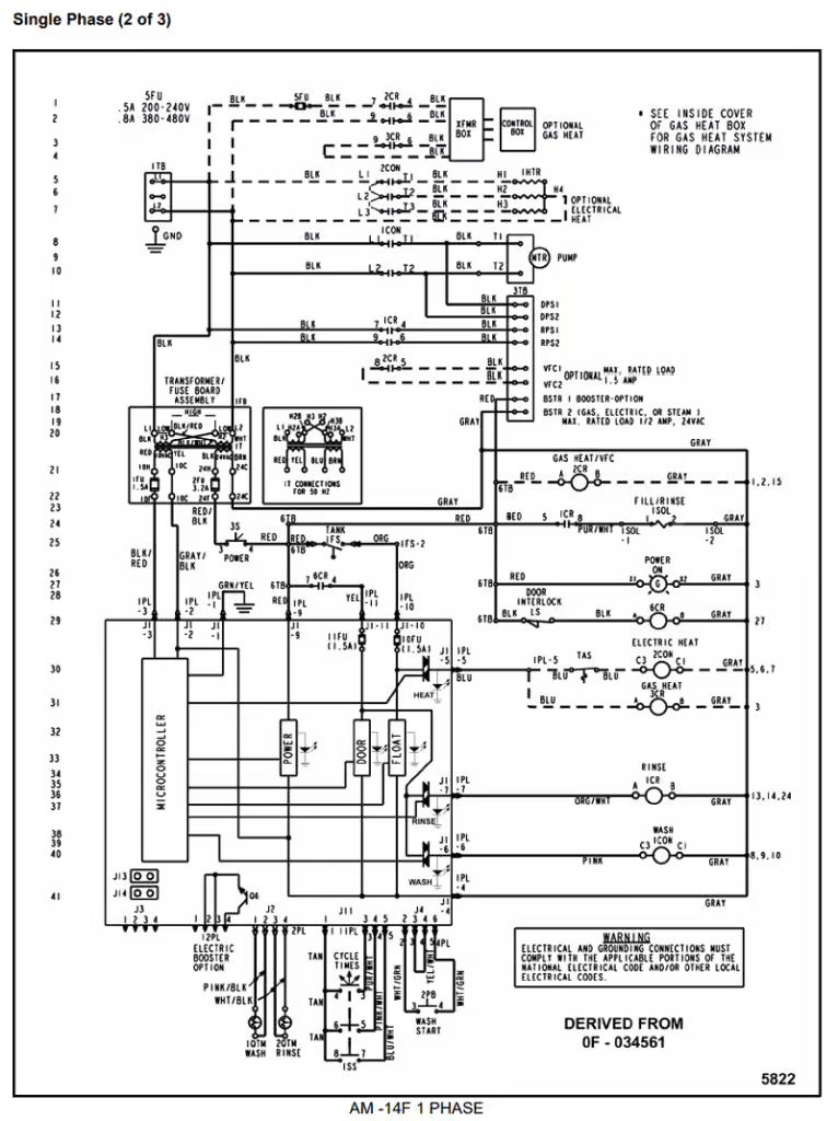
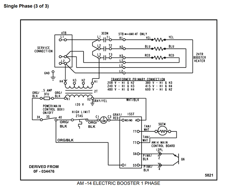
1 Phase Diagrams
The following 1 phase wiring diagrams are for the Hobart 14 AM series dishwashers:
AM 14, AM 14C, AM 14T, AM 14TC
AM 14F
AM 14 Electric Booster
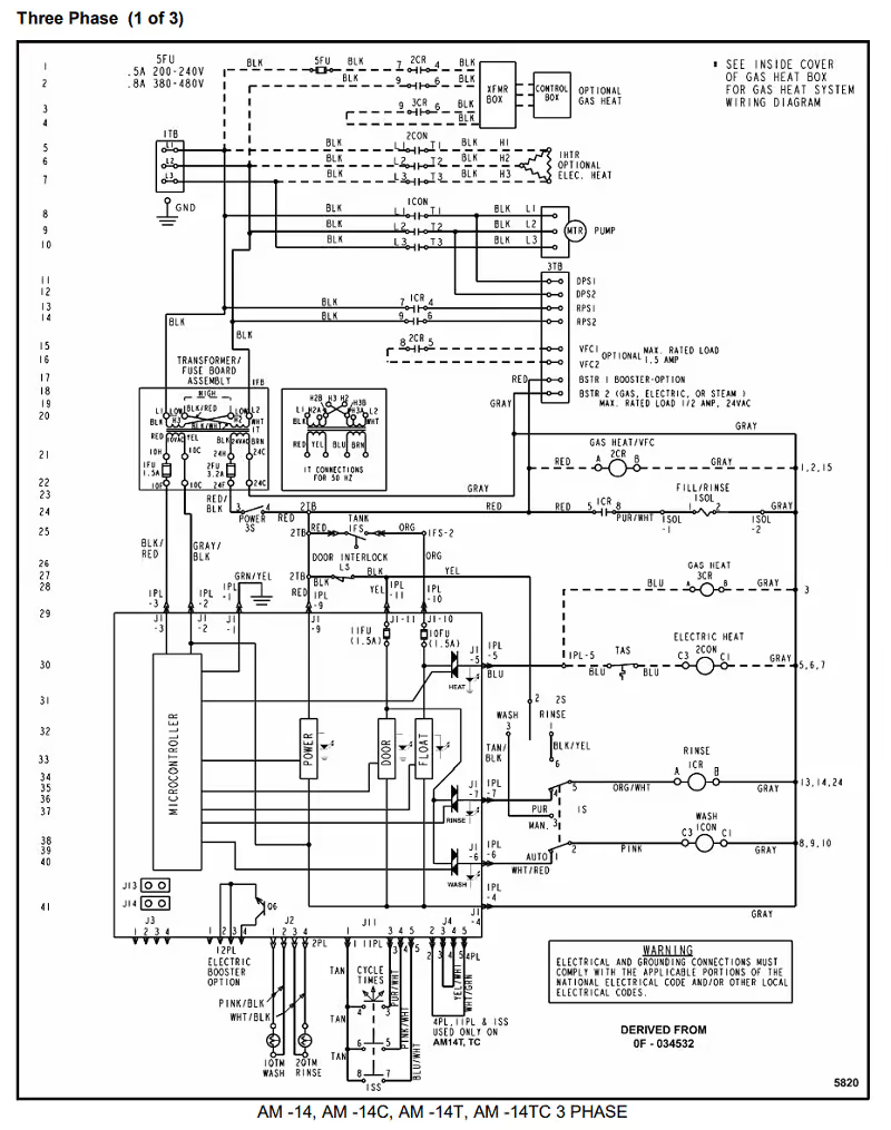
3 Phase Diagrams
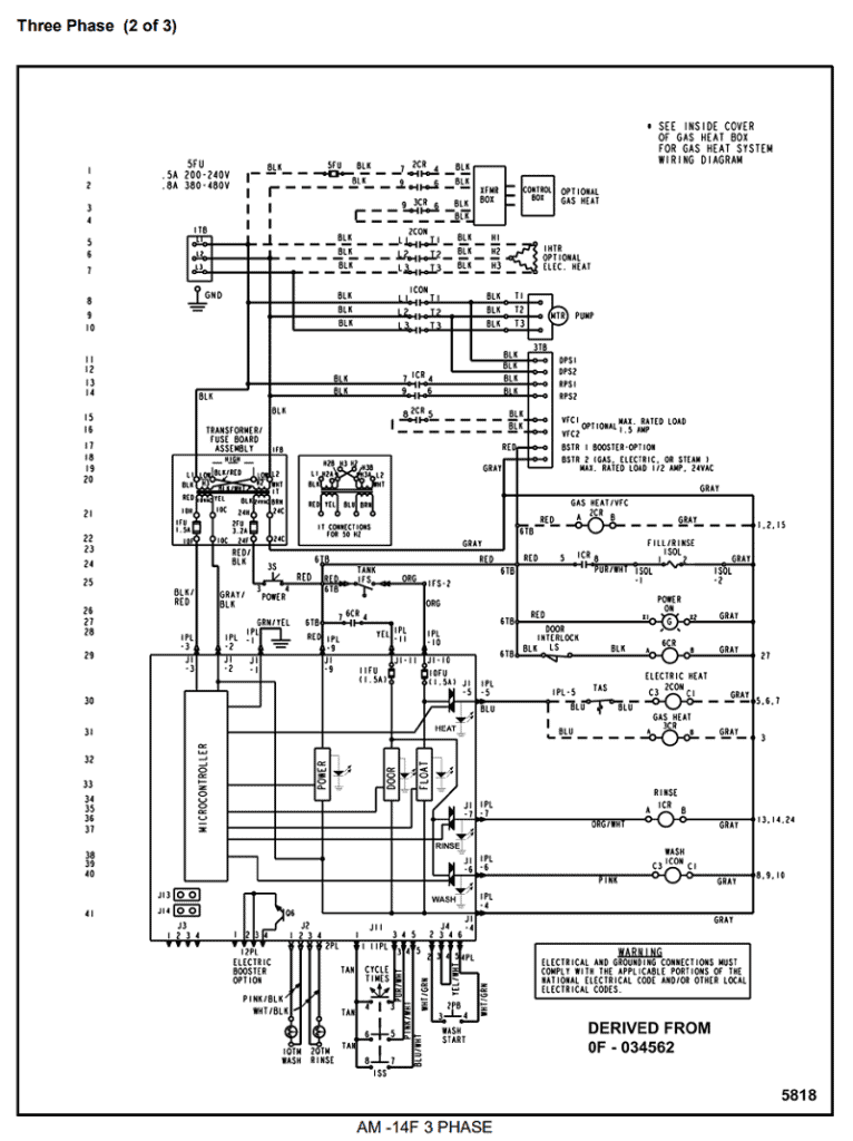
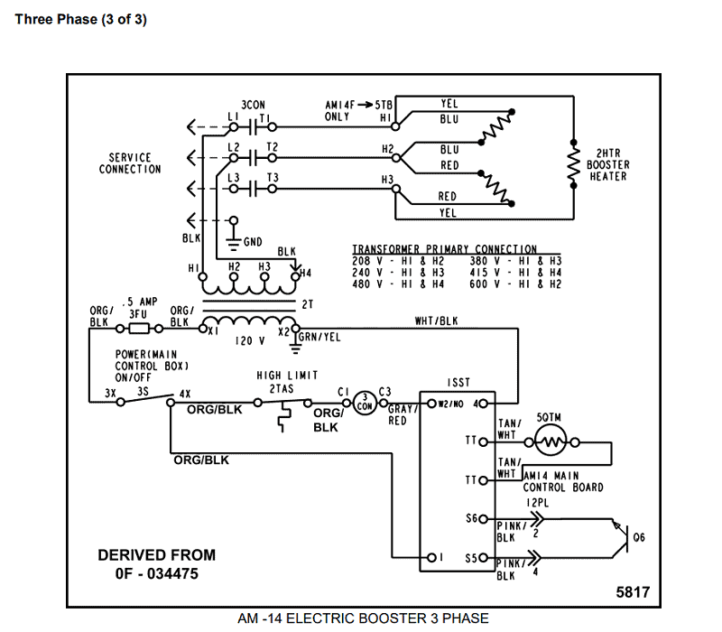
The following 3 phase wiring diagrams are for the Hobart 14 AM series dishwashers:
AM 14, AM 14C, AM 14T, AM 14TC
AM 14F
AM 14 Electric Booster
*Source: SERVICE MANUAL SUPPLEMENT AM 14 SERIES and 13 kW ELECTRIC BOOSTER OPTION (pages 21-26)
